How a Turbocharger Works (Boost, Lag, and Wastegates)
A turbocharger is an air pump driven by exhaust you were about to throw away. How the turbine, compressor, wastegate and intercooler work, with measured curves.
An engine throws away most of the energy in its fuel. A good chunk goes out of the exhaust pipe as hot, fast-moving gas: pressure and heat that cost you fuel to make and then leave without doing any work.
A turbocharger steals some of it back. It puts a small windmill in the exhaust stream and uses that windmill to drive an air pump feeding the intake. The engine ends up breathing air it could not have drawn on its own.
Quick Answer: How Does a Turbocharger Work?
Exhaust gas leaving the engine spins a turbine wheel. That turbine is bolted to one end of a shaft; on the other end of the same shaft is a compressor wheel, which sucks in outside air and forces it into the engine under pressure. More air in each cylinder means more fuel can burn with it, which means more power from the same engine.
Wastegates, intercoolers, blow-off valves, and turbo lag all follow from the awkward details of making those two wheels behave.
What Does a Turbocharger Do
A turbocharger uses the engine's own exhaust to spin a compressor that packs more air into the cylinders. More air per cycle burns more fuel per cycle, and that is more power from the same displacement. It adds nothing else: no extra swept volume, no extra rpm, only denser air, and everything below is what that costs and how it is controlled.
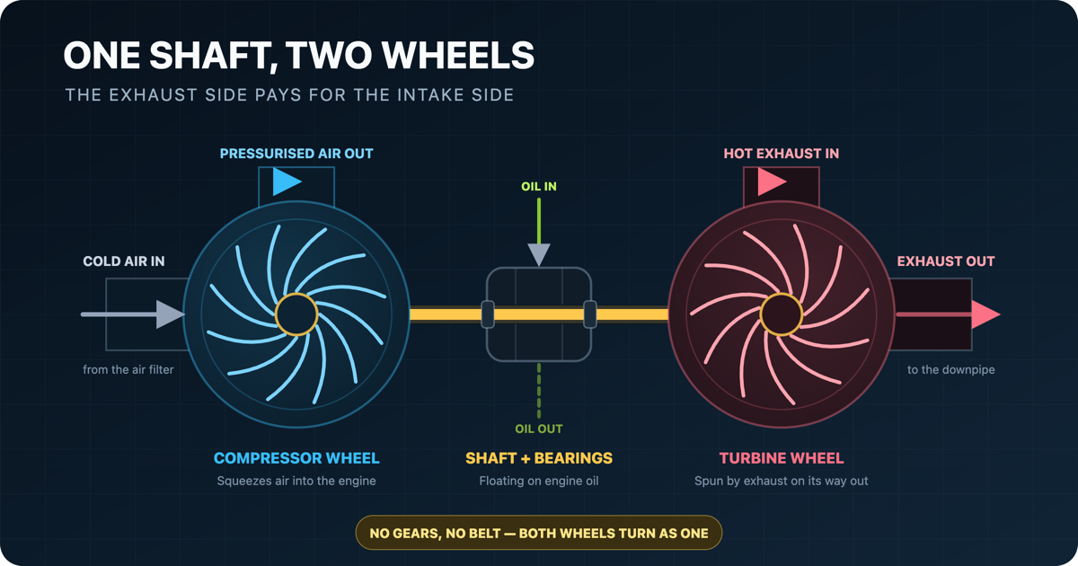
A turbo is smaller than most people expect: on a family car, about the size of a grapefruit. It has three sections bolted together in a line, and the cutaway at the top of this page shows all three: a compressor wheel on the left, a turbine wheel on the right, and a bearing housing between them.
The detail that explains almost every turbo behaviour is that the two wheels are on one shaft. There is no gearbox, no clutch, no belt, no control over their relative speed. Whatever the turbine does, the compressor does. If the turbine is turning at 90,000 rpm, so is the compressor, whether the engine wants that much air or not.
Between them sits a bearing housing fed with engine oil. The shaft does not run on ball bearings in the usual sense; it floats on a film of pressurized oil, because at these speeds nothing else survives. Garrett quotes shaft speeds of up to 350,000 rpm for its smallest units, with a point on the wheel rim travelling over 1,900 km/h, in exhaust gas reaching 1,900 °F.
A real one, a diesel turbo, with the compressor inlet facing you and the compressor wheel visible down inside it:
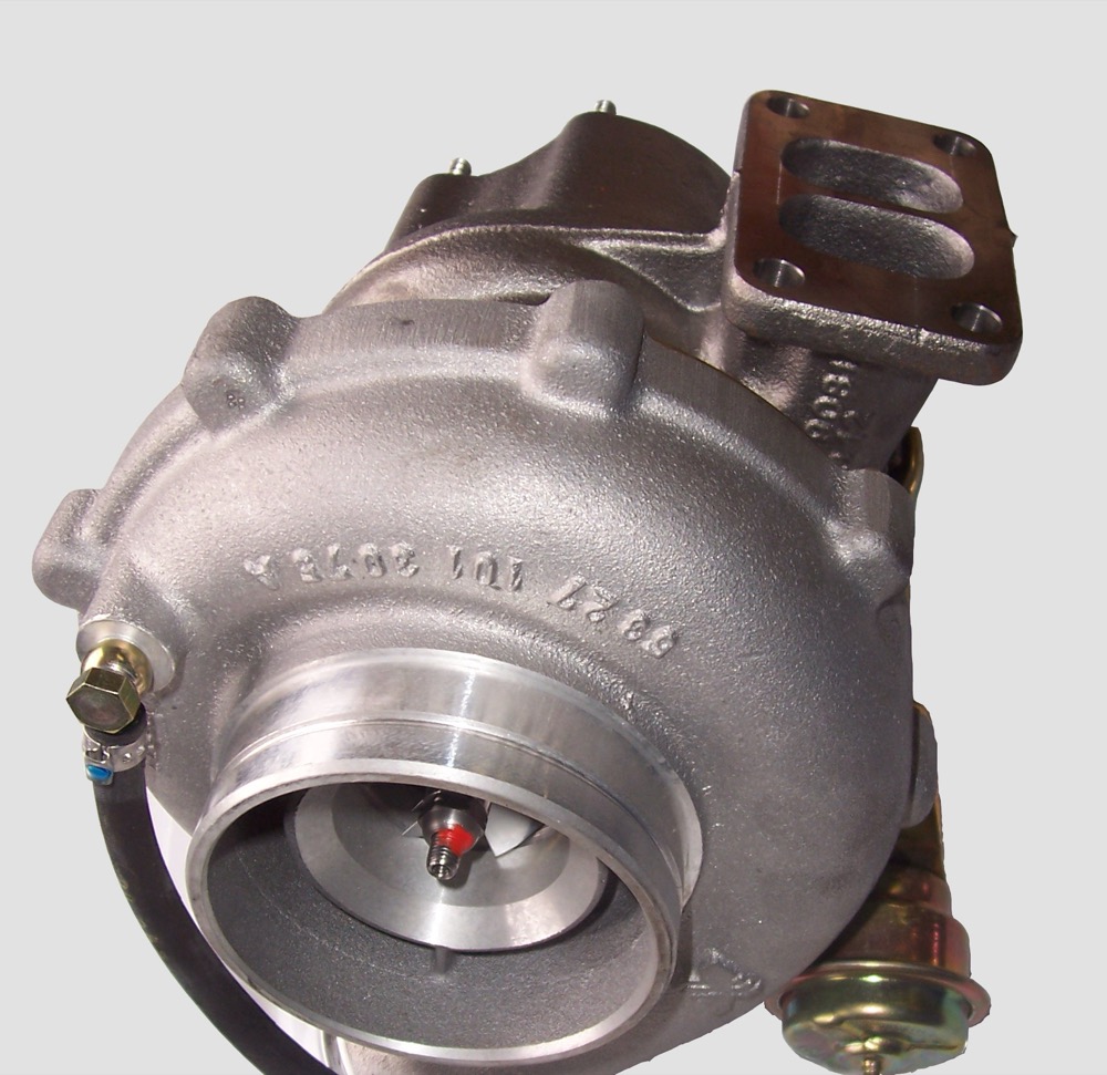
A diesel turbocharger. The round opening is the compressor inlet, with the wheel just inside it. The flange at top right is where exhaust enters. The gold canister lower right is the wastegate actuator, covered below. (Photo: Panoha, CC BY-SA 3.0)

The idea is old. Swiss engineer Alfred Büchi filed a German patent in 1905 for a compound engine with a compressor and an exhaust turbine on a common shaft; Brown Boveri delivered the first commercial heavy-duty exhaust-gas turbocharger, the VT402, in June 1924. Aircraft got there long before cars did: General Electric began developing superchargers after a 1917 request from the NACA for a way to improve high-altitude flying, and by the Second World War the NACA's Aircraft Engine Research Laboratory had an entire division working on them.
How It Plumbs Into the Engine
A turbo is more than a bolt-on accessory hanging off the side. It sits in the middle of two circuits at once, the intake and the exhaust, and joins them together.
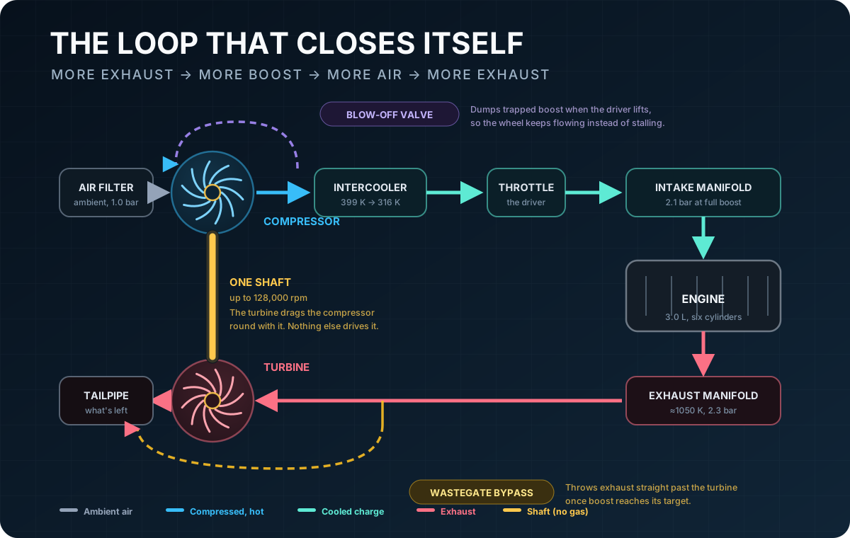
Follow the air. It comes in through the filter, the compressor squeezes it, the intercooler cools it, it passes the throttle, and it fills the intake manifold. It burns. It leaves through the exhaust manifold, hits the turbine, and goes down the tailpipe.
This is a loop. More exhaust spins the turbine harder, which drives the compressor harder, which pushes more air into the engine, which produces more exhaust. A turbocharger is a positive feedback system with its own throttle in the middle of it, and most of what follows is about keeping that loop under control.
Why More Air Means More Power
An engine is an air pump with a fixed swept volume. At a given rpm it draws a fixed volume per minute. Power comes from burning fuel, and how much fuel you can burn depends on the mass of oxygen you have to burn it with.
That mass is the volume times the density of the charge, and density follows the ideal gas law:
ρ = p / (R · T)
Double the pressure at constant temperature and you double the density: twice the air in the same cylinder, twice the fuel, roughly twice the power. That is the entire proposition. The same law moves a naturally aspirated dyno reading with the weather; the dyno correction calculator undoes it.
Read the equation again. Density depends on pressure divided by temperature, and compressing air heats it. That T in the denominator is the reason the next section exists, and it is the part most explanations skip.
Compressing Air Makes It Hot
Squeezing a gas raises its temperature whether you want it to or not. Measured on the simulator's turbocharged 3.0-litre six at redline, air enters the compressor at 293 K (20 °C) and leaves it at 399 K, 126 °C, hot enough to burn you, from nothing but being pressurized to 2.2 bar absolute.
An ideal, loss-free compressor doing the same job would reach 367 K. The extra 32 K is wasted work: the compressor is about 69% efficient, and the shortfall shows up as heat. So you pay twice: once in heat you did not want, and again because that heat has thinned out the air you were trying to thicken.
The fix is a heat exchanger between compressor and engine, the intercooler (or charge-air cooler). On the same measured engine it takes the charge from 399 K back down to 316 K. Working the density out at the manifold pressure of 2.19 bar:
| Temperature | Charge density | Versus ambient | |
|---|---|---|---|
| Ambient air | 293 K | 1.19 kg/m³ | 1.00× |
| After compressor, no cooler | 399 K | 1.91 kg/m³ | 1.61× |
| After intercooler | 316 K | 2.42 kg/m³ | 2.03× |
The intercooler is worth about 26% more air at the same boost pressure, and it does that without asking the turbo to spin any faster. Cooler charge also resists engine knock, which sets the real ceiling on the whole exercise.
A real compressor wheel, under measurement at NACA's Aircraft Engine Research Laboratory in 1944. The curved vanes throw air outward; the housing catches it and turns velocity into pressure:
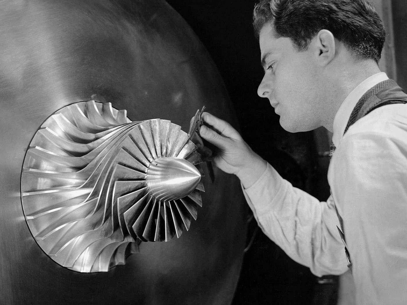
A researcher in the Supercharger Research Division measures blade thickness on a supercharger impeller, January 1944. (Photo: NASA, image GRC-1944-C-03814)
Turbo Lag Is a Mass Problem
Ask most people what turbo lag is and they say "the delay before the boost comes in", which is true and explains nothing. The useful question is a delay caused by what?
The rotor has mass. Spinning it up takes torque applied over time, and the torque available depends on how much exhaust energy the engine is producing at that moment, which is little at the instant you have asked for full throttle from low load. Lag is Newton's second law applied to a spinning wheel: the rotor is accelerating, and boost arrives when it gets there.
You can watch it happen. A measured trace: the simulator's turbo six held at a fixed 2500 rpm, throttle snapped from closed to wide open at t = 0.
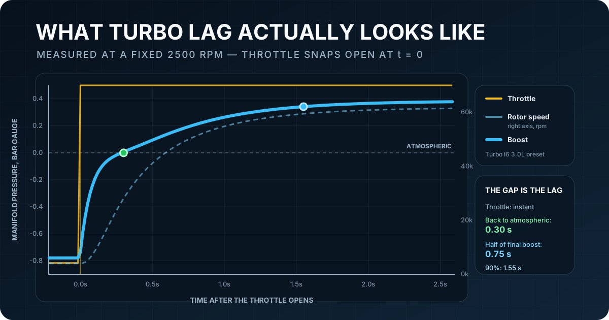
The throttle is a step. Boost is a curve. Manifold pressure takes 0.30 s to climb back to atmospheric, 0.75 s to reach half its final value, and 1.55 s to get to 90%. Over that time the rotor goes from 4,000 rpm to 61,600 rpm.
Look at the two curves together: boost tracks the rotor, not the pedal. The pressure curve is the speed curve, redrawn. Engineers attack lag by attacking rotor inertia: smaller and lighter wheels, ceramic or titanium-aluminide turbines, twin small turbos instead of one big one, or an electric motor on the shaft to spin it up before the exhaust can.
The Wastegate: Why Boost Does Not Run Away
Return to that feedback loop. More exhaust makes more boost makes more exhaust. Left alone, a turbo at high rpm would keep accelerating until it destroyed itself or the engine.
So you fit a wastegate: a flap in the exhaust, upstream of the turbine, that lets exhaust gas bypass the turbine. Open the flap, less gas goes through the wheel, the rotor slows, boost falls. Garrett describes it as sitting on the exhaust manifold before the turbine housing inlet, with spring ratings from about 0.2 to 1.7 bar.
That spring matters. In its classic form a wastegate is a spring pushing a flap shut and a diaphragm sensing boost pressure pushing it open. It is a proportional device with no memory, which has a consequence people often mistake for a fault: to hold itself open, it needs a standing pressure error. More flow needs more opening needs more overpressure. So boost does not pin to a flat line; it creeps upward with engine speed.
Measured on the simulator's turbo six at wide-open throttle:
| Engine speed | Boost (gauge) | Wastegate open | Rotor speed |
|---|---|---|---|
| 1200 rpm | 0.03 bar | 0% | 19,800 rpm |
| 2000 rpm | 0.16 bar | 0% | 41,000 rpm |
| 2500 rpm | 0.38 bar | 0% | 61,400 rpm |
| 3000 rpm | 1.02 bar | 6% | 93,700 rpm |
| 4000 rpm | 1.12 bar | 33% | 99,600 rpm |
| 7000 rpm | 1.19 bar | 55% | 106,400 rpm |
Below 3000 rpm the gate never cracks: the turbo is making less boost than the spring is set for, so there is nothing to bleed. Past that the gate does all the work, opening progressively to a bit over half travel, while boost still drifts up by 0.17 bar. That drift is the standing error, and it is real hardware behaviour rather than a modelling artefact.
Surge: The Compressor's Forbidden Zone
A compressor has a narrow comfort zone. Like a wing, its blades have a range of angles at which flow stays attached, and pushing outside that range breaks the flow down.
Engineers draw that as a compressor map: airflow across the bottom, pressure ratio up the side, and the boundaries of good behaviour marked on it.
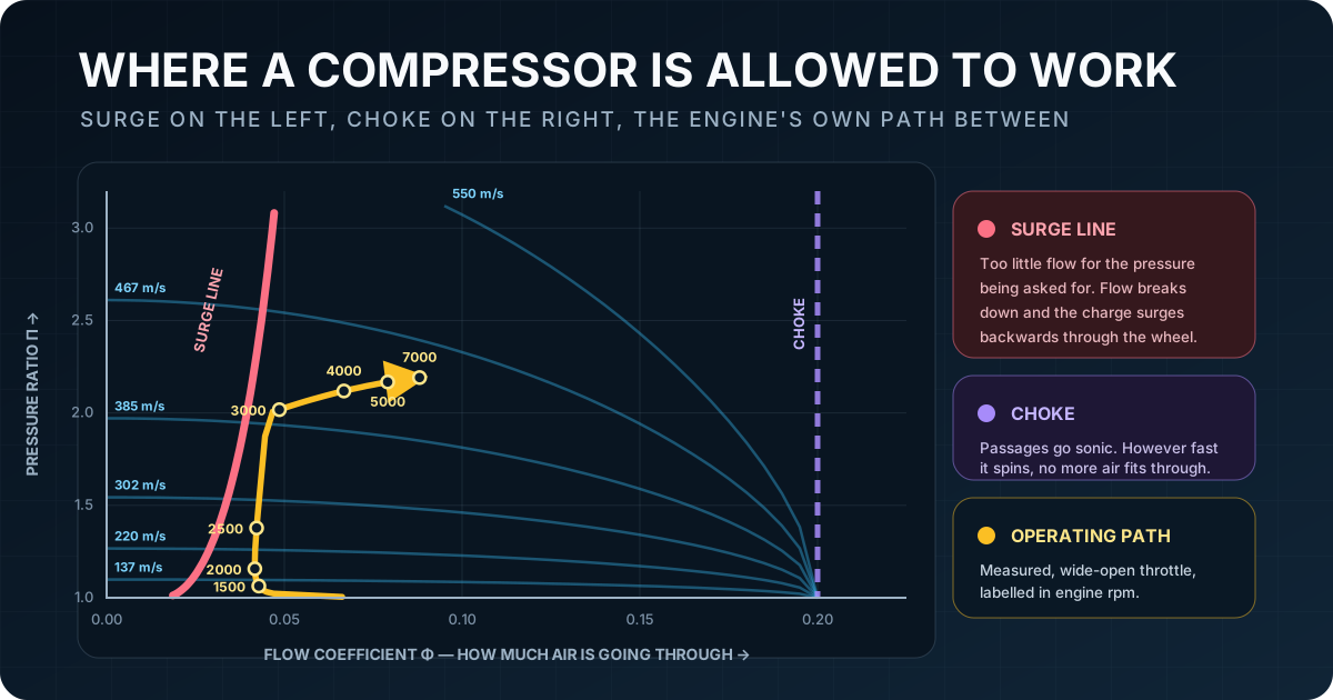
Two walls bound the useful region:
- Surge, on the left. Too little flow for the pressure ratio being demanded. Flow separates from the blades and the compressor can no longer hold back the pressurized air downstream of it; in a deep surge, flow briefly reverses back through the wheel. Pressure then collapses, forward flow re-establishes, and the whole thing repeats, which is what makes surge an audible fluttering rather than a single event.
- Choke, on the right. Flow through the passages reaches the speed of sound. Beyond this no amount of extra shaft speed pushes more air.
The yellow line is the engine's own path, measured across a wide-open-throttle sweep and labelled in engine rpm. It hugs the surge line and climbs almost vertically through 2500–3000 rpm. That near-vertical section is the spool, the compressor gaining pressure much faster than it gains flow. Then it turns right and walks along the top as engine airflow grows.
The surge line also rises to the right. A faster wheel needs proportionally more throughflow to stay stable; the surge boundary is not a fixed amount of airflow. We got that wrong once: an earlier version of this simulator used a flat surge threshold and reported surge at wide-open throttle, through the part of the rev range where the engine was pulling hardest.
Jet engines have the same problem on a much larger scale, and they share the vocabulary, though not always the same physical event. In a multistage axial compressor, flow can separate in individual blade passages and form rotating stall cells that orbit the annulus while the engine as a whole keeps flowing forward, a different thing from a system-wide surge. That distinction has its own article: compressor stall vs surge.
Where the Blow-Off Valve Comes In
Picture lifting off the throttle at full boost. The throttle plate slams shut. Between the compressor and that plate sits a pipe full of pressurized air, and a rotor at 100,000 rpm that cannot stop quickly. Flow goes to nearly zero while pressure ratio stays high: the operating point jumps left, straight into surge.
The blow-off valve (or recirculation valve) is the escape hatch. It senses the pressure trapped against the shut throttle and opens, dumping that air either to atmosphere (the familiar hiss) or back to the compressor inlet. The wheel keeps flowing, and the compressor stays out of surge.
In the simulator, snapping the throttle shut at 4500 rpm and full boost opens the valve for about 0.12 s, during which measured compressor flow increases as the trapped charge escapes through it. The valve then reseats, and the still-spinning rotor does briefly enter surge as it winds down. A blow-off valve buys you the transient; it does not repeal the map.
The Bill: Backpressure and Compression Ratio
A turbo is paid for twice.
First, the turbine is a restriction. Before it is a source of power it is an obstruction in the exhaust, and the engine has to push against it. On the measured turbo six, exhaust manifold pressure climbs from 1.08 bar at 1200 rpm to 2.79 bar at redline. Above about 3500 rpm it is higher than intake manifold pressure, 2.79 bar against 2.19 at the top end, and the engine is pumping uphill on every exhaust stroke.
There is a window where the opposite holds. Between roughly 2500 and 3500 rpm the boost the compressor is making outruns the backpressure the turbine is causing, and the measured pumping work goes negative: the gas exchange does work on the pistons instead of costing them. The band is narrow (at 3000 rpm the engine sees 2.02 bar in the intake against 1.86 in the exhaust), but it is real, it is the sign of a well-matched turbo, and it is a large part of why turbodiesels are as efficient as they are. Outside that window, at idle and at redline alike, the turbine is charging rent.
Second, and more expensively, you have to give back compression ratio. Cramming denser, hotter air into a cylinder pushes the end-gas closer to auto-igniting on its own, which is knock, and knock is destructive. The standard defence is to lower the geometric compression ratio, and lowering compression ratio lowers thermal efficiency, as the Otto cycle makes plain. DOE-funded work by MIT's John Heywood puts it squarely: high compression and high boost together are limited by the onset of engine knock, and knock suppression, rather than turbine technology, unlocks the remaining efficiency.
The simulator's turbocharged six runs 8.5:1 while its naturally aspirated twin runs 11.0:1 for this reason. You can see it in the torque curves:
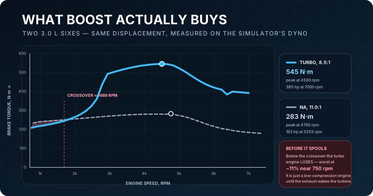
Above the crossover the turbo engine roughly doubles the naturally aspirated one: 545 N·m against 283, 385 hp against 193, from the same 3.0 litres. That is 128 hp per litre against 64.
Look below 1688 rpm. There the turbocharged engine is down on the naturally aspirated one, by up to 11%. With no boost yet, it is a 3.0-litre six with unusually low compression. Everything it gains, it gains by spinning the turbine, and until it does, low compression is all you have. This is the trade a turbocharged engine makes, and it is why manufacturers care so much about spool time.
How Much Horsepower Does a Turbocharger Add
As much as the boost it runs, less the compression it gave up. The density law above says power follows absolute manifold pressure, so a turbo holding 1 bar of boost is asking for roughly double, and the two engines we have measured both land near that:
| Engine | Boost at redline | No turbo | With turbo | Gain |
|---|---|---|---|---|
| 3.0 L six, 8.5:1 | 1.19 bar | 162.77 hp | 385.48 hp | +137% |
| 6.17 L V8, 9.5:1 | 0.70 bar | 338.65 hp | 612.51 hp | +80.9% |
The six is the same engine with the turbo removed and its 8.5:1 kept, measured in does a bigger turbo mean more lag; the V8 is the FIT button's turbo on a stock 6.2, sized to what 98 octane allows, from supercharger vs turbocharger. Neither is a rule, and the density law is a ceiling rather than an answer. The six ends at 2.19 bar absolute and gains more than that ratio; the V8 ends at 1.70 bar, because its wastegate is set for 0.45 bar of boost and creeps to 0.70 by redline, and gains less. Three things pull the number off the ratio: the intercooler leaves the charge at 316 K, 8% thinner than the pressure alone says; the turbine's backpressure takes its cut at the top of the range; and the gain is measured against a baseline the lower compression ratio already weakened. Against the 11.0:1 naturally aspirated six the honest comparison is 193 hp to 385, the doubling in the chart above, because the 30 hp between 193 and 162.77 is what the lower compression ratio cost before the turbo paid anything back.
Try It in the Simulator
All of the measurements above came out of the engine simulator on this site, and you can reproduce them in the browser.
Watch boost chase the throttle. Open the Turbo I6 3.0L, start it, and hold a steady mid-range rpm. Now go wide open and watch the Boost, Turbo and Wastegate rows in the gauge panel. Boost climbs behind rotor speed, and the wastegate reads 0% until the turbo reaches its set point, then starts opening.
See the intercooler working. The Charge cooled row appears whenever the cooler has something to do, and reads compressor discharge → post-cooler temperature: around 399 → 316 K at the top of the range. The IAT row is what the engine swallows.
See what the turbine costs. Watch the Exhaust row against MAP as revs rise. They cross twice: exhaust pressure leads at low rpm, MAP overtakes it through the midrange, and exhaust wins again above about 3500 rpm. The Pump row is the same story as a single number. It dips negative between roughly 2500 and 3500 rpm, the gas exchange doing work on the pistons rather than costing them, and climbs positive after that.
Watch the operating point move. The turbo map panel plots the live compressor point against the same surge and choke boundaries drawn above. Lift off the throttle sharply at high boost and watch it dart left toward the surge line.
Compare against the naturally aspirated twin. The Inline-6 3.0L is the same displacement at 11.0:1. Run the dyno on both.
Try to fit a turbo to an engine that cannot take one. In the spec panel of any piston engine there is a FIT TURBOCHARGER button, sized from displacement and capped at what that engine's compression and fuel will safely take. On the naturally aspirated 3.0-litre six at 11.0:1 on 95 octane, the button is disabled and reads TOO MUCH COMPRESSION FOR BOOST: this engine has no knock margin left to spend. Drop its compression ratio and the button lights up.
The most instructive case is the LPG inline-four: it runs an even higher 11.5:1, and it accepts a turbo, because its fuel is 110 octane. Same compression and a different fuel give the opposite answer.
Or start from a turbodiesel. The Turbo Diesel V8 6.7L keeps 17:1 compression, because a diesel has no knock limit to run from. Boost goes almost straight into torque, and it makes 1,248 N·m just above 2000 rpm.
What This Model Does and Does Not Do
The simulator runs a mean-value turbocharger model: rotor inertia integrated against turbine and compressor torque, an ellipse compressor map, a blade-speed-ratio turbine, a proportional wastegate, a charge pipe with a blow-off valve, and an intercooler. It is a reduced-order teaching model, not manufacturer data or a matching tool.
Three limits, stated plainly:
- Exhaust temperature is computed from combustion on petrol engines only. The simulator now computes a petrol engine's exhaust temperature from the burn: it rises with speed and spark retard, and it falls to charge temperature when the ignition is cut, so boost now sags on the rev limiter. Petrol turbine inlet temperature reads about 1,250–1,340 K at full throttle, hotter than real engines that enrich for power. Diesels still schedule it from the fuel lever, at 1,050 K at full load.
- The exhaust is one lumped manifold feeding one wheel. There is no exhaust pulse separation, so twin-scroll housings and pulse tuning are outside the model, as is variable-geometry turbine hardware.
- Turbine outlet temperature is not modelled, so anything downstream of the wheel reads the inlet temperature.
None of that changes the mechanisms described above, but the numbers in this article are the model's numbers. Where a figure is a real-world value we cite it; where we measured it from the simulator, the text says so.
Turbocharger FAQs
What is the difference between a turbocharger and a supercharger?
Both are compressors that force air into an engine. A turbine in the exhaust stream drives a turbocharger; the crankshaft drives a supercharger mechanically, usually by a belt or gears. The turbo recovers otherwise-wasted exhaust energy, so it costs less power to run, but it responds more slowly because the turbine has to spin up first. A supercharger responds at once and consumes crankshaft power the whole time it is turning.
Why do turbocharged engines have lower compression ratios?
Because boost and compression stack. Both raise the pressure and temperature of the end-gas before the spark, and past a limit that gas ignites on its own, which is knock. Reducing the geometric compression ratio buys back the margin that boost consumes. It costs thermal efficiency, which is why higher-octane fuel, direct injection and good intercooling are all worth paying for: each lets you keep more compression while running the same boost.
Does a blow-off valve make a car faster?
No. It is a protection device. It stops the compressor being driven into surge when the throttle shuts, which protects the shaft and bearings and keeps the rotor spinning for the next application of throttle. Venting it to atmosphere rather than recirculating it makes the noise; on many production cars the same valve is plumbed back into the inlet and is nearly silent.
How hot does a turbocharger get?
Very. Garrett cites exhaust gas up to 1,900 °F (about 1,040 °C) at the turbine. The turbine housing glowing visibly red under hard use is normal. It is also why oil supply matters so much: the bearing housing sits between a red-hot turbine and the oil film keeping the shaft alive.
Why do some turbo engines feel laggy and others do not?
Rotor inertia and turbine sizing. A large turbine wheel makes more power at high flow but needs more exhaust energy to get moving, so it spools late; a small one spools fast and then runs out of breath. Manufacturers dodge the trade-off with two small turbos instead of one big one, twin-scroll housings that keep exhaust pulses from interfering, variable-geometry turbines that change the effective housing size on the fly, or an electric motor on the shaft.
Sources and Further Reading
- Garrett Motion: What Is a Turbo and How Does It Work?
- Garrett Motion: What is the difference between a wastegate and a blow-off valve?
- Accelleron: 100 Years of Industrial Turbocharging (Büchi's 1905 patent; the 1924 BBC VT402)
- US DOE / J. Heywood, MIT: High Compression Ratio Turbo Gasoline Engine Operation Using Alcohol Enhancement (knock as the limit on boost and compression)
- NASA image library: Supercharger Research at the Aircraft Engine Research Laboratory, 1944
Related Reading
- Does a bigger turbo really mean more lag? — five compressor wheels on this same six, timed to boost; the spool trace above, taken apart by wheel size
- Supercharger vs turbocharger: which makes more power? — the belt-driven alternative fitted to one V8 beside a turbo, with the exhaust tax measured
- What Is Engine Knock? Causes, Sounds, and How to Stop It
- The Otto Cycle Explained: Thermodynamics of the Gasoline Engine
- Compressor Stall vs Surge in Jet Engines
- How a Four-Stroke Engine Works (All 4 Strokes Explained)